Showing posts with label PIC. Show all posts
Showing posts with label PIC. Show all posts
Tuesday, April 17, 2012
Microcontroller Programmer DIY
I search about this issue for a while, "Building programmer of our own designs". I found a few of open source programmer projects so that every body can use and contribute it. Here is an opportunity of learning the microcontroller programmer designs from that open schematics. (more…)

Monday, October 12, 2009
PIC Wireless Networks Wifi (Hotspot) Detector

This wireless detector project allows you to sense the presence and relative signal strength of wireless hotspots. It is "always on" and communicates the presence and signal strength of an in-range hotspot by way of sequences of pulses - like a heartbeat you can feel. The stronger and faster the "heartbeat", the stronger the wireless signal detected.
This project consists of a microcontroller PIC 12F629, some custom interface electronics, a small vibe motor, and an off-the-shelf Wi-Fi detector from D-Link. The microcontroller periodically "presses" the button on the detector to initiate a reading. The microcontroller "reads" the output from the detector indicator LEDs and uses this as the basis for pulsing out a signal on the vibe motor, which the wearer can feel.
tag : wireless networks, hotspot detector, Wi-Fi strength signal indicator src
Thursday, September 17, 2009
Simple PIC RF/Microwave Frequency Counter

There are 3 inpust on this project a microwave (prescaled) input, an RF input and a TTL input. The microwave and RF inputs are AC coupled and terminated to a low impedance (around 50ohms). The TTL input is DC coupled and has a high input impedance. A progress-bar indicator is provided on the LCD for the gate timing.
Both the microwave and RF inputs have an additional feature : a simple signal-level detector driving yet another bar indicator on the LCD module. This is very useful to check for the correct input-signal level as well as an indicator for circuit tuning or absorption-wave-meter dip display (Lecher wires). This project designed by Matjaz Vidmar.
tag : RF counter, Microwave Frequency counter, PIC project source
Simple PIC RF/Microwave Frequency Counter
There are 3 inpust on this project a microwave (prescaled) input, an RF input and a TTL input. The microwave and RF inputs are AC coupled and terminated to a low impedance (around 50ohms). The TTL input is DC coupled and has a high input impedance. A progress-bar indicator is provided on the LCD for the gate timing.
Both the microwave and RF inputs have an additional feature : a simple signal-level detector driving yet another bar indicator on the LCD module. This is very useful to check for the correct input-signal level as well as an indicator for circuit tuning or absorption-wave-meter dip display (Lecher wires). This project designed by Matjaz Vidmar.
tag : RF counter, Microwave Frequency counter, PIC project source
Sunday, August 2, 2009
PIC Cactus LED Display

LEDactus is LED display project that resemble Cactus. It used PIC microcontroller 18F1320 as controller of the LED. LEDactus is immobile and attempts to survive by creating a pleasant display. It can produce more complex and mesmerizing displays. And in the latest generations, a sense of touch is added to allow the LEDactus to interact with passersby.
term : LED display, electronic cactus, PIC project (src)
PIC Cactus LED Display
LEDactus is LED display project that resemble Cactus. It used PIC microcontroller 18F1320 as controller of the LED. LEDactus is immobile and attempts to survive by creating a pleasant display. It can produce more complex and mesmerizing displays. And in the latest generations, a sense of touch is added to allow the LEDactus to interact with passersby.
term : LED display, electronic cactus, PIC project (src)
Tuesday, June 30, 2009
PIC LCD Oscilloscope for Spectrum Analyzers

This is simple and inexpensive LCD oscilloscope for spectrum analyzer display. The project use PIC 16F876A as main processor. Although a small LCD screen is not as good as analog oscilloscope, a LCD oscilloscope may be very useful in field measurements, for battery operation or you need different measurement at the same time along with oscilloscope.
The 80dB scale of this LCD oscilloscope can be adjusted with the two trimmers providing the reference voltages to the A/D converter. The operation of the LCD oscilloscope is slightly different between the 80dB mode and the 40dB mode. In the 80dB mode, the trace is always visible and saturates on the bottom or top of screen. In the 40dB mode, the trace runs out of the screen and only the central part of the original 80dB scale is displayed. This project designed by Matjaz Vidmar.
Download
Source code, documentation and schematic
tags : LCD, Oscilloscope, Spectrum Analyzer, PIC, microcontroller, project src
PIC LCD Oscilloscope for Spectrum Analyzers
This is simple and inexpensive LCD oscilloscope for spectrum analyzer display. The project use PIC 16F876A as main processor. Although a small LCD screen is not as good as analog oscilloscope, a LCD oscilloscope may be very useful in field measurements, for battery operation or you need different measurement at the same time along with oscilloscope.
The 80dB scale of this LCD oscilloscope can be adjusted with the two trimmers providing the reference voltages to the A/D converter. The operation of the LCD oscilloscope is slightly different between the 80dB mode and the 40dB mode. In the 80dB mode, the trace is always visible and saturates on the bottom or top of screen. In the 40dB mode, the trace runs out of the screen and only the central part of the original 80dB scale is displayed. This project designed by Matjaz Vidmar.
Download
Source code, documentation and schematic
tags : LCD, Oscilloscope, Spectrum Analyzer, PIC, microcontroller, project src
Wednesday, June 24, 2009
USB PIC Programmer

Usbpicprog is an USB in circuit programmer for Microchip PIC processors. The hardware is as simple. The latest version only contains one PIC18F2550, 3 mosfets, and besides the connectors a hand full of passive components.
download
Open source programmer
USB PIC Programmer
Usbpicprog is an USB in circuit programmer for Microchip PIC processors. The hardware is as simple. The latest version only contains one PIC18F2550, 3 mosfets, and besides the connectors a hand full of passive components.
download
Open source programmer
Sunday, June 14, 2009
PIC Low Cost USB-CAN Distributed Motion Control System

This project presents high performance distributed motion control system at extremely low cost. Rapid prototyping of multi-axis designs is often required during the development of automation equipment. One can use centralized controls with PC motion control cards, external amplifiers, and a tangle of wires, or utilize existing high cost distributed motion control system with RS485, Ethernet, or one of the fieldbuses (DeviceNet, CANOpen, Profibus, etc.). With the use of highly integrated microcontrollers, such as the PIC18FXX8, and power devices like the Allegro A3977/A3959, a very small and inexpensive system was developed.
Download
document and schematic
tag : motion control system, USB, PIC project src
PIC Low Cost USB-CAN Distributed Motion Control System
This project presents high performance distributed motion control system at extremely low cost. Rapid prototyping of multi-axis designs is often required during the development of automation equipment. One can use centralized controls with PC motion control cards, external amplifiers, and a tangle of wires, or utilize existing high cost distributed motion control system with RS485, Ethernet, or one of the fieldbuses (DeviceNet, CANOpen, Profibus, etc.). With the use of highly integrated microcontrollers, such as the PIC18FXX8, and power devices like the Allegro A3977/A3959, a very small and inexpensive system was developed.
Download
document and schematic
tag : motion control system, USB, PIC project src
Tuesday, May 12, 2009
PICTalker - Low Cost PIC Speech Synthesizer

PICTalker is a low cost allophone-based system for synthesis speech. The system use PIC16F628 microcontroller as main processor. You need a PIC development system and programmer, and Microsoft QBasic to program the microcontroller and EEPROMs to build this poject.
Speech quality is somewhat inferior to that from an SPO256 system. Most people immediately understand most or all of the speech it produces provided sufficient care is taken when constructing words from the component allophones. The speech is significantly easier to understand if the loudspeaker used has poor base response.
Download
Documentation and source code
tag : low cost speech synthesizer, PIC project (src)
PICTalker - Low Cost PIC Speech Synthesizer
PICTalker is a low cost allophone-based system for synthesis speech. The system use PIC16F628 microcontroller as main processor. You need a PIC development system and programmer, and Microsoft QBasic to program the microcontroller and EEPROMs to build this poject.
Speech quality is somewhat inferior to that from an SPO256 system. Most people immediately understand most or all of the speech it produces provided sufficient care is taken when constructing words from the component allophones. The speech is significantly easier to understand if the loudspeaker used has poor base response.
Download
Documentation and source code
tag : low cost speech synthesizer, PIC project (src)
Thursday, April 23, 2009
Digital Clock using Classic LED 7 Segment Displays

This is a simple digital clock project using PIC16F887 and classic LED 7-Segment from HP 5082-7414 created by punkky. The displays are bright red and sun light viewable. Each clock consumes about 0.25W (50mA, 5V) when the PIC16F887 operates at 250kHz (display refresh rate is about 61Hz).
Tag: digital clock, 7 segment display, PIC project src
Digital Clock using Classic LED 7 Segment Displays
This is a simple digital clock project using PIC16F887 and classic LED 7-Segment from HP 5082-7414 created by punkky. The displays are bright red and sun light viewable. Each clock consumes about 0.25W (50mA, 5V) when the PIC16F887 operates at 250kHz (display refresh rate is about 61Hz).
Tag: digital clock, 7 segment display, PIC project src
Tuesday, April 21, 2009
PIC Debugging Tool
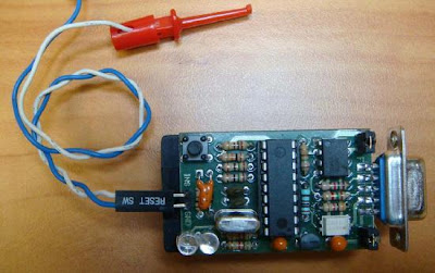
In-Circuit-Debugger is handy and easy PIC debugging tool for PIC programmers that interface to the target PIC placed- board. The device comes with MPLAB plug-ins that provides a full rich set of commands and functions in order to debug your code in real time. The project created by Electrical Engineer Atanasios Melimopoulos.
After hours of using some brands of ICDs, ICD2, etc. on different projects, I faced some hardware situations where the two pin interface ICD <-> PIC becomes annoying and sometimes difficult to work around. Apart from the fact that your target PIC must run at selected clock frequencies that allows the ICD-Uart baudrate multiplier to fit. Also, some pics do not allow the same on-hook commands upon which ICDs are based. There is no electrical isolation between the pic-target board and the USB–Serial PC-GND interface.
Download
In-Circuit-debugger
tag : PIC debugger, PIC programmer tools, PIC project src
PIC Debugging Tool
In-Circuit-Debugger is handy and easy PIC debugging tool for PIC programmers that interface to the target PIC placed- board. The device comes with MPLAB plug-ins that provides a full rich set of commands and functions in order to debug your code in real time. The project created by Electrical Engineer Atanasios Melimopoulos.
After hours of using some brands of ICDs, ICD2, etc. on different projects, I faced some hardware situations where the two pin interface ICD <-> PIC becomes annoying and sometimes difficult to work around. Apart from the fact that your target PIC must run at selected clock frequencies that allows the ICD-Uart baudrate multiplier to fit. Also, some pics do not allow the same on-hook commands upon which ICDs are based. There is no electrical isolation between the pic-target board and the USB–Serial PC-GND interface.
Download
In-Circuit-debugger
tag : PIC debugger, PIC programmer tools, PIC project src
Subscribe to:
Posts (Atom)


