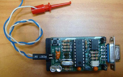
Download : schematic, verilog source code, uip port
tag : AVR, Project, WLAN, Data Transfer, Wireless Project, Microcontroller Design (src)
Microchip Provides Micro Controller and Analog Semiconductors, with Low-risk Product Development, Lower Total System Cost and Faster Time To Market
Microchip/Circuit cellar have announced a 16 bit embedded control design contest - the idea is to promote the use of the dsPIC family of controllers.
Microchip is giving out a generous sample of components to the contest participants - here is what I got:
I find the ENC28J60 device very interesting - it’s an ethernet controller using which your microcontroller can communicate over an ethernet LAN!
Any good ideas to create a prize winning entry?
Completed interfacing an LCD panel with the USB PIC, thanks to Anish. We are still not able to get interrupt URB’s working properly - except that, everything is OK.
Coming next: A comprehensive tutorial on developing USB gadgets with GNU/Linux and PIC! We hope to get it published as an LDP HOWTO.
It’s no wonder that there are so few complete resources on writing USB firmware on the net - there is only one word to describe the process - `tedious’.
The last few days have been spent reading USB Complete - this is the only good book available to help you get along … it’s extremely well written. This book, combined with the code ofPUF framework seems to be the best combination for getting started. Another great resource is the code written by Bradley A Minch available from here. I prefer the PUF code because it’s better structured - but there seems to be some trouble with the configuration bit definition in it.
Our development environment is now stable. The programmer, `odyssey’, is working perfectly and SDCC + gputils seems to be generating correct code. Unfortunately, we were unable to get PUF running on our 18F2455. So we began taking out bits and pieces of code from PUF and started testing them independently. We were able to go as far as initializing endpoint 0 and getting an OUT transaction on it. Now the trouble with USB is that it has a tricky state machine - the way you handle the current transaction depends on what the previous transaction was. You will soon reach a point where you won’t be able to test things with 10-20 lines of code - you will have to have the whole state machine running smoothly. So yesterday, Anish `cleaned up’ the PUF code taking out a lot of things which were not going to be useful for us at present but keeping the core intact. And, magically, everything started working. Enumeration was succesful and we have endpoint 0 ready to accept control transfter requests!
Understanding Microchip’s description of the working of their USB SIE (Serial Interface Engine) is another headache.
Now we have to get some `vendor’ requests working and maybe configure another endpoint to do interrupt transfer. I will think of writing a proper tutorial after that.
Even though USB has become wildly popular, there are not too many resources on the web which gives you a tutorial introduction on how to go about developing USB peripherals and controlling them with GNU/Linux. Anish and myself have started work on creating a simple USB gadget - we intend to document the process thoroughly so that others can do the same with the mininum of effort.
Choosing the proper microcontroller and setting up a decent development environment is the first headache. When it comes to USB aware uC’s, there is not too much of a choice - it seems that the USB PIC18F devices are the only ones commonly available in India. We purchased a few PIC18F2455 devices from Future Techniks. These are 28 pin devices which are USB 2.0 compliant. Now comes the issue of finding out a proper `burning’ software and hardware. The trouble is that most of them are written for Windows. Anish was succesful in running Free PicPgm under Wine. But I am not satisfied until I find a a 100% GNU/Linux solution. We spent lots of time exploring various possibilities which included using bootloaders - Microchip has an `official’ bootloader whose working is fully documented. The trouble is that there is no GNU/Linux frontend for it - so we had to write a Python program to parse Hex files and deliver it to the bootloader in the proper format - the effort was abandoned midway because we thought it would take some time to test the code thoroughly.
Luckily, we discovered Odyssey, a very well written program for downloading code to PIC devices. It works well with the classical David Tait high voltage PIC programmer. Only trouble was creating two config files - one which describes the hardware (which parallel port pin controls which pin on the PIC) and another one which describes the PIC18F2455 device (device id, config bit masks, amount of code memory etc). The programmer has been working reliably for the past two days.
Now comes the issue of choosing development tools - PIC’s are usually programmed in assembly - they have a bizarre architecture which makes them unfriendly to C compilers. But Microchip has brought out a few changes in the 18F family - it’s said that these changes make the processor more compiler friendly. Anyway, I wish to avoid assembly coding as far as possible. The only freely available C compiler for the PIC’s is SDCC which has support for PIC18F devices. We used a version of the compiler bundled with PUF - the PIC USB Framework. It seems the compiler is not very good at generating compact code - but let’s hope it does a good job generating code! We did a few tests yesterday - and they were OK. But the linker, `gplink’ seems to be having a bug (is it a bug - not sure). SDCC lets us declare arrays in program memory space by using the `code’ directive. Thus, we can do:correct
code unsigned char a[] = {0xe, 0xd, 0xe, 0xef};
This places data in the `code’ section of the resulting object file. The linker, `gplink’, objects to this and generates an assertion failure when it tries to produce a list file.
Download
Source and PDF
These IC’s and the Avago galvanic isolators are truly the "enabling technology" for this project. The controller IC is also used to perform system health checks, and set the operating points of the individual vacuum tubes. This allows total system programmability, offering several possible preset operating modes.
Download
Project Documentation
Remote controls usually consist of encoder/decoder parts connected to a transmitter/receiver module which takes care of the transmission of digital signals by radio or infra waves. The format of this project's signal is designed to be ideal even for the cheapest ASK RF modules (using 50% signal/silence ratio), and it is similar to the Philips RC-5 format used in infrared remote controls. The transmitter has a varying number of buttons and sends the states of these inputs to the receiver. The receiver device decodes the message and sets the outputs accordingly.
Download schematic IR(jpeg), schematic RF
source
Among the Amateur Radio fraternity, a device such as the one described here would otherwise be known as a Field Strength Meter (FSM). Its main purpose would be to check that RF power is being radiated from a transmitting antenna. Some FSMs are tuneable across a wide range of frequencies, which allows the device to work with different transmitters and antennae - usually from HF to VHF and beyond. A difference with this unit is that it is only sensitive to those signals in the R/C section of the radio spectrum. The on-board trimmer allows you to tweak for maximum signal strength of your frequency of choice, whether it be 27MHz AM, or 40MHz FM.
In order to read the received signal strength, such a unit would ordinarily employ a mechanical analogue meter. The unit described here differs in that it uses four super-bright LEDs. The benefit of this is that it allows you to read the display from a distance - even in bright sunlight.
Download schematic(gif), PCB1, PCB2
The sensor array consists of 4 touch sensors on the bottom of each foot, Left and right IR obstacle detection, and 4 CdS photo detectors located on all four sides of the robot. The heart of the control system is a Microchip PIC16F819 micro-controller and a separate 8 channel A-D converter.
The mechanical structure is built from brass tubing (which all the wiring runs through, UHMW (a high density plastic material), and PCBs. Perhaps the most striking aspect of the robot is the use of PCBs to create a 3D structure and mount all of the circuits/electronics.
tag : robotic design,PIC, Microcontroller, Electronic (src)